256Mb: 16 Meg x 16, 8 Meg x 32 Mobile SDRAM
Features
Mobile Low-Power SDR SDRAM
MT48H16M16LF – 4 Meg x 16 x 4 banks
MT48H8M32LF – 2 Meg x 32 x 4 banks
Features
Options
Marking
• VDD/VDDQ: 1.8V/1.8V
• Addressing
– Standard addressing option
• Configuration
– 16 Meg x 16 (4 Meg x 16 x 4 banks)
– 8 Meg x 32 (2 Meg x 32 x 4 banks)
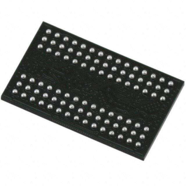
• Plastic “green” packages
– 54-ball VFBGA (8mm x 9mm)1
– 90-ball VFBGA (8mm x 13mm)2
• Timing – cycle time
– 6ns @ CL = 3
– 7.5ns @ CL = 3
• Operating temperature range
– Commercial (0˚C to +70˚C)
– Industrial (–40˚C to +85˚C)
• Revision
• VDD/VDDQ = 1.7–1.95V
• Fully synchronous; all signals registered on positive
edge of system clock
• Internal, pipelined operation; column address can
be changed every clock cycle
• Four internal banks for concurrent operation
• Programmable burst lengths: 1, 2, 4, 8, and continuous
• Auto precharge, includes concurrent auto precharge
• Auto refresh and self refresh modes
• LVTTL-compatible inputs and outputs
• On-chip temperature sensor to control self refresh
rate
• Partial-array self refresh (PASR)
• Deep power-down (DPD)
• Selectable output drive strength (DS)
• 64ms refresh period
Notes:
H
LF
16M16
8M32
BF
B5
-6
-75
None
IT
:H
1. Available only for x16 configuration.
2. Available only for x32 configuration.
Table 1: Configuration Addressing
Architecture
16 Meg x 16
8 Meg x 32
Number of banks
4
4
Bank address balls
BA0, BA1
BA0, BA1
Row address balls
A[12:0]
A[11:0]
Column address balls
A[8:0]
A[8:0]
Table 2: Key Timing Parameters
Speed
Grade
1
Access Time
CL = 2
CL = 3
CL = 2
CL = 3
-6
104
166
8.0ns
5.0ns
-75
104
133
8.0ns
5.4ns
Note:
PDF: 09005aef834c13d2
256mb_mobile_sdram_y36n.pdf - Rev. J 09/10 EN
Clock Rate (MHz)
1. CL = CAS (READ) latency
Micron Technology, Inc. reserves the right to change products or specifications without notice.
© 2008 Micron Technology, Inc. All rights reserved.
Products and specifications discussed herein are subject to change by Micron without notice.
�256Mb: 16 Meg x 16, 8 Meg x 32 Mobile SDRAM
Features
Figure 1: 256Mb Mobile LPSDR Part Numbering
MT
48
H 16M16 LF
BF
Micron Technology
-6
IT
:H
Revision
:H
Product Family
Operating Temperature
48 = Mobile SDR SDRAM
Blank = Commercial (0°C to +70°C)
Operating Voltage
IT = Industrial (–40°C to +85°C)
H = 1.8V/1.8V
Cycle Time
Configuration
-6 = 6ns tCK, CL = 3
16 Meg x 16
-75 = 7.5ns tCK, CL = 3
8 Meg x 32
Package Codes
Addressing
BF = 8mm x 9mm VFBGA “green”
LF = Mobile standard addressing
B5 = 8mm x 13mm VFBGA “green”
FBGA Part Marking Decoder
Due to space limitations, FBGA-packaged components have an abbreviated part marking that is different from the
part number. Micron’s FBGA part marking decoder is available at www.micron.com/decoder.
PDF: 09005aef834c13d2
256mb_mobile_sdram_y36n.pdf - Rev. J 09/10 EN
2
Micron Technology, Inc. reserves the right to change products or specifications without notice.
© 2008 Micron Technology, Inc. All rights reserved.
�256Mb: 16 Meg x 16, 8 Meg x 32 Mobile SDRAM
Features
Contents
General Description ......................................................................................................................................... 8
Functional Block Diagram ................................................................................................................................ 9
Ball Assignments and Descriptions ................................................................................................................. 10
Package Dimensions ...................................................................................................................................... 13
Electrical Specifications .................................................................................................................................. 15
Absolute Maximum Ratings ........................................................................................................................ 15
Electrical Specifications – IDD Parameters ........................................................................................................ 17
Electrical Specifications – AC Operating Conditions ......................................................................................... 20
Output Drive Characteristics ........................................................................................................................... 23
Functional Description ................................................................................................................................... 26
Commands .................................................................................................................................................... 27
COMMAND INHIBIT .................................................................................................................................. 28
NO OPERATION (NOP) .............................................................................................................................. 28
LOAD MODE REGISTER (LMR) ................................................................................................................... 28
ACTIVE ...................................................................................................................................................... 28
READ ......................................................................................................................................................... 29
WRITE ....................................................................................................................................................... 30
PRECHARGE .............................................................................................................................................. 31
BURST TERMINATE ................................................................................................................................... 31
AUTO REFRESH ......................................................................................................................................... 31
SELF REFRESH ........................................................................................................................................... 32
DEEP POWER-DOWN ................................................................................................................................ 32
Truth Tables ................................................................................................................................................... 33
Initialization .................................................................................................................................................. 38
Mode Register ................................................................................................................................................ 40
Burst Length .............................................................................................................................................. 41
Burst Type ................................................................................................................................................. 41
CAS Latency ............................................................................................................................................... 43
Operating Mode ......................................................................................................................................... 43
Write Burst Mode ....................................................................................................................................... 43
Extended Mode Register ................................................................................................................................. 44
Temperature-Compensated Self Refresh ..................................................................................................... 44
Partial-Array Self Refresh ............................................................................................................................ 45
Output Drive Strength ................................................................................................................................ 45
Bank/Row Activation ...................................................................................................................................... 46
READ Operation ............................................................................................................................................. 47
WRITE Operation ........................................................................................................................................... 56
Burst Read/Single Write .............................................................................................................................. 63
PRECHARGE Operation .................................................................................................................................. 64
Auto Precharge ........................................................................................................................................... 64
AUTO REFRESH Operation ............................................................................................................................. 76
SELF REFRESH Operation .............................................................................................................................. 78
Power-Down .................................................................................................................................................. 80
Deep Power-Down ......................................................................................................................................... 81
Clock Suspend ............................................................................................................................................... 82
Revision History ............................................................................................................................................. 85
Rev. J, Production – 09/10 ........................................................................................................................... 85
Rev. I, Production – 11/09 ........................................................................................................................... 85
Rev. H, Production – 10/09 .......................................................................................................................... 85
Rev. G, Production – 8/09 ............................................................................................................................ 85
PDF: 09005aef834c13d2
256mb_mobile_sdram_y36n.pdf - Rev. J 09/10 EN
3
Micron Technology, Inc. reserves the right to change products or specifications without notice.
© 2008 Micron Technology, Inc. All rights reserved.
�256Mb: 16 Meg x 16, 8 Meg x 32 Mobile SDRAM
Features
Rev. F, Production – 6/09 ............................................................................................................................
Rev. E, Production – 4/09 ............................................................................................................................
Rev. D, Production – 1/09 ...........................................................................................................................
Rev. C, Production – 12/08 ..........................................................................................................................
Rev. B, Preliminary – 10/08 .........................................................................................................................
Rev. A, Advance – 9/08 ................................................................................................................................
Revision History for Commands, Operations, and Timing Diagrams .............................................................
Update – 10/08 ...........................................................................................................................................
Update – 7/08 ............................................................................................................................................
Update – 5/08 ............................................................................................................................................
Update – 4/08 ............................................................................................................................................
PDF: 09005aef834c13d2
256mb_mobile_sdram_y36n.pdf - Rev. J 09/10 EN
4
85
85
85
85
85
85
85
85
86
86
86
Micron Technology, Inc. reserves the right to change products or specifications without notice.
© 2008 Micron Technology, Inc. All rights reserved.
�256Mb: 16 Meg x 16, 8 Meg x 32 Mobile SDRAM
Features
List of Figures
Figure 1: 256Mb Mobile LPSDR Part Numbering .............................................................................................. 2
Figure 2: Functional Block Diagram ................................................................................................................. 9
Figure 3: 54-Ball VFBGA (Top View) ............................................................................................................... 10
Figure 4: 90-Ball VFBGA (Top View) ............................................................................................................... 11
Figure 5: 54-Ball VFBGA (8mm x 9mm) .......................................................................................................... 13
Figure 6: 90-Ball VFBGA (8mm x 13mm) ......................................................................................................... 14
Figure 7: Typical Self Refresh Current vs. Temperature ................................................................................... 19
Figure 8: ACTIVE Command .......................................................................................................................... 28
Figure 9: READ Command ............................................................................................................................. 29
Figure 10: WRITE Command ......................................................................................................................... 30
Figure 11: PRECHARGE Command ................................................................................................................ 31
Figure 12: Initialize and Load Mode Register .................................................................................................. 39
Figure 13: Mode Register Definition ............................................................................................................... 40
Figure 14: CAS Latency .................................................................................................................................. 43
Figure 15: Extended Mode Register Definition ................................................................................................ 44
Figure 16: Example: Meeting tRCD (MIN) When 2 < tRCD (MIN)/tCK < 3 ......................................................... 46
Figure 17: Consecutive READ Bursts .............................................................................................................. 48
Figure 18: Random READ Accesses ................................................................................................................ 49
Figure 19: READ-to-WRITE ............................................................................................................................ 50
Figure 20: READ-to-WRITE With Extra Clock Cycle ......................................................................................... 51
Figure 21: READ-to-PRECHARGE .................................................................................................................. 51
Figure 22: Terminating a READ Burst ............................................................................................................. 52
Figure 23: Alternating Bank Read Accesses ..................................................................................................... 53
Figure 24: READ Continuous Page Burst ........................................................................................................ 54
Figure 25: READ – DQM Operation ................................................................................................................ 55
Figure 26: WRITE Burst ................................................................................................................................. 56
Figure 27: WRITE-to-WRITE .......................................................................................................................... 57
Figure 28: Random WRITE Cycles .................................................................................................................. 58
Figure 29: WRITE-to-READ ............................................................................................................................ 58
Figure 30: WRITE-to-PRECHARGE ................................................................................................................. 59
Figure 31: Terminating a WRITE Burst ........................................................................................................... 60
Figure 32: Alternating Bank Write Accesses .................................................................................................... 61
Figure 33: WRITE – Continuous Page Burst .................................................................................................... 62
Figure 34: WRITE – DQM Operation ............................................................................................................... 63
Figure 35: READ With Auto Precharge Interrupted by a READ ......................................................................... 65
Figure 36: READ With Auto Precharge Interrupted by a WRITE ....................................................................... 66
Figure 37: READ With Auto Precharge ............................................................................................................ 67
Figure 38: READ Without Auto Precharge ....................................................................................................... 68
Figure 39: Single READ With Auto Precharge .................................................................................................. 69
Figure 40: Single READ Without Auto Precharge ............................................................................................. 70
Figure 41: WRITE With Auto Precharge Interrupted by a READ ....................................................................... 71
Figure 42: WRITE With Auto Precharge Interrupted by a WRITE ...................................................................... 71
Figure 43: WRITE With Auto Precharge .......................................................................................................... 72
Figure 44: WRITE Without Auto Precharge ..................................................................................................... 73
Figure 45: Single WRITE With Auto Precharge ................................................................................................ 74
Figure 46: Single WRITE Without Auto Precharge ........................................................................................... 75
Figure 47: Auto Refresh Mode ........................................................................................................................ 77
Figure 48: Self Refresh Mode ......................................................................................................................... 79
Figure 49: Power-Down Mode ....................................................................................................................... 80
Figure 50: Clock Suspend During WRITE Burst ............................................................................................... 82
PDF: 09005aef834c13d2
256mb_mobile_sdram_y36n.pdf - Rev. J 09/10 EN
5
Micron Technology, Inc. reserves the right to change products or specifications without notice.
© 2008 Micron Technology, Inc. All rights reserved.
�256Mb: 16 Meg x 16, 8 Meg x 32 Mobile SDRAM
Features
Figure 51: Clock Suspend During READ Burst ................................................................................................ 83
Figure 52: Clock Suspend Mode ..................................................................................................................... 84
PDF: 09005aef834c13d2
256mb_mobile_sdram_y36n.pdf - Rev. J 09/10 EN
6
Micron Technology, Inc. reserves the right to change products or specifications without notice.
© 2008 Micron Technology, Inc. All rights reserved.
�256Mb: 16 Meg x 16, 8 Meg x 32 Mobile SDRAM
Features
List of Tables
Table 1: Configuration Addressing ................................................................................................................... 1
Table 2: Key Timing Parameters ...................................................................................................................... 1
Table 3: VFBGA Ball Descriptions .................................................................................................................. 12
Table 4: Absolute Maximum Ratings .............................................................................................................. 15
Table 5: DC Electrical Characteristics and Operating Conditions ..................................................................... 15
Table 6: Capacitance ..................................................................................................................................... 16
Table 7: IDD Specifications and Conditions (x16) ............................................................................................ 17
Table 8: IDD Specifications and Conditions (x32) ............................................................................................ 17
Table 9: IDD7 Specifications and Conditions (x16 and x32) ............................................................................... 18
Table 10: Electrical Characteristics and Recommended AC Operating Conditions ............................................ 20
Table 11: AC Functional Characteristics ......................................................................................................... 21
Table 12: Target Output Drive Characteristics (Full Strength) .......................................................................... 23
Table 13: Target Output Drive Characteristics (Three-Quarter Strength) .......................................................... 24
Table 14: Target Output Drive Characteristics (One-Half Strength) ................................................................. 25
Table 15: Truth Table – Commands and DQM Operation ................................................................................ 27
Table 16: Truth Table – Current State Bank n, Command to Bank n ................................................................. 33
Table 17: Truth Table – Current State Bank n, Command to Bank m ................................................................ 35
Table 18: Truth Table – CKE .......................................................................................................................... 37
Table 19: Burst Definition Table .................................................................................................................... 42
PDF: 09005aef834c13d2
256mb_mobile_sdram_y36n.pdf - Rev. J 09/10 EN
7
Micron Technology, Inc. reserves the right to change products or specifications without notice.
© 2008 Micron Technology, Inc. All rights reserved.
�256Mb: 16 Meg x 16, 8 Meg x 32 Mobile SDRAM
General Description
General Description
The 256Mb Mobile LPSDR is a high-speed CMOS, dynamic random-access memory containing 268,435,456 bits. It is internally configured as a quad-bank DRAM with a synchronous interface (all signals are registered on the positive edge of the clock signal, CLK).
Each of the x16’s 67,108,864-bit banks is organized as 8192 rows by 512 columns by 16
bits. Each of the x32’s 67,108,864-bit banks is organized as 4096 rows by 512 columns by
32 bits.
Note:
1. Throughout the data sheet, various figures and text refer to DQs as DQ. DQ should be
interpreted as any and all DQ collectively, unless specifically stated otherwise. Additionally, the x16 is divided into two bytes: the lower byte and the upper byte. For the lower
byte (DQ[7:0]), DQM refers to LDQM. For the upper byte (DQ[15:8]), DQM refers to
UDQM. The x32 is divided into four bytes. For DQ[7:0], DQM refers to DQM0. For
DQ[15:8], DQM refers to DQM1. For DQ[23:16], DQM refers to DQM2, and for
DQ[31:24], DQM refers to DQM3.
2. Complete functionality is described throughout the document; any page or diagram
may have been simplified to convey a topic and may not be inclusive of all requirements.
3. Any specific requirement takes precedence over a general statement.
PDF: 09005aef834c13d2
256mb_mobile_sdram_y36n.pdf - Rev. J 09/10 EN
8
Micron Technology, Inc. reserves the right to change products or specifications without notice.
© 2008 Micron Technology, Inc. All rights reserved.
�256Mb: 16 Meg x 16, 8 Meg x 32 Mobile SDRAM
Functional Block Diagram
Functional Block Diagram
Figure 2: Functional Block Diagram
CKE
CLK
Control
logic
Command
decode
CS#
WE#
CAS#
RAS#
BA1
0
0
1
1
EXT mode
register
Mode register
Bank1
Refresh
counter
Bank0
row
address
latch
and
decoder
Row
address
MUX
Bank2
Address
BA0, BA1
Address
register
2
DQM
n
Data
output
register
n
n
DQ
Data
input
register
Column
decoder
Column/
address
counter/
latch
PDF: 09005aef834c13d2
256mb_mobile_sdram_y36n.pdf - Rev. J 09/10 EN
Bank3
I/O gating
DQM mask logic
read data latch
write drivers
Bank
control
logic
Bank
0
1
2
3
Bank0
memory
array
Sense amplifiers
2
BA0
0
1
0
1
9
Micron Technology, Inc. reserves the right to change products or specifications without notice.
© 2008 Micron Technology, Inc. All rights reserved.
�256Mb: 16 Meg x 16, 8 Meg x 32 Mobile SDRAM
Ball Assignments and Descriptions
Ball Assignments and Descriptions
Figure 3: 54-Ball VFBGA (Top View)
1
2
3
VSS
DQ15
DQ14
4
5
6
7
8
9
VSSQ
VDDQ
DQ0
VDD
DQ13
VDDQ
VSSQ
DQ2
DQ1
DQ12
DQ11
VSSQ
VDDQ
DQ4
DQ3
DQ10
DQ9
VDDQ
VSSQ
DQ6
DQ5
DQ8
DNU1
VSS
VDD
LDQM
DQ7
UDQM
CLK
CKE
CAS#
RAS#
WE#
A12
A11
A9
BA0
BA1
CS#
A8
A7
A6
A0
A1
A10
VSS
A5
A4
A3
A2
VDD
A
B
C
D
E
F
G
H
J
Note:
PDF: 09005aef834c13d2
256mb_mobile_sdram_y36n.pdf - Rev. J 09/10 EN
1. The E2 pin must be connected to VSS, VSSQ, or left floating.
10
Micron Technology, Inc. reserves the right to change products or specifications without notice.
© 2008 Micron Technology, Inc. All rights reserved.
�256Mb: 16 Meg x 16, 8 Meg x 32 Mobile SDRAM
Ball Assignments and Descriptions
Figure 4: 90-Ball VFBGA (Top View)
1
2
3
DQ26
DQ24
VSS
4
5
6
7
8
9
VDD
DQ23
DQ21
A
A
B
B
DQ28
VDDQ
VSSQ
VDDQ
VSSQ
DQ19
C
C
VSSQ
DQ27
DQ25
DQ22
DQ20
VDDQ
VSSQ
DQ29
DQ30
DQ17
DQ18
VDDQ
D
D
E
E
VDDQ
DQ31
NC
NC
DQ16
VSSQ
F
F
VSS
DQM3
A3
A2
DQM2
VDD
A4
A5
A6
A10
A0
A1
A7
A8
A12
A13
BA1
A11
G
G
H
H
J
J
CLK
CKE
A9
BA0
CS#
RAS#
DQM1
DNU1
NC
CAS#
WE#
DQM0
VDDQ
DQ8
VSS
VDD
DQ7
VSSQ
K
K
L
L
M
M
VSSQ
DQ10
DQ9
DQ6
DQ5
VDDQ
VSSQ
DQ12
DQ14
DQ1
DQ3
VDDQ
DQ11
VDDQ
VSSQ
VDDQ
VSSQ
DQ4
N
N
P
P
R
R
DQ13
Note:
PDF: 09005aef834c13d2
256mb_mobile_sdram_y36n.pdf - Rev. J 09/10 EN
DQ15
VSS
VDD
DQ0
DQ2
1. The K2 pin must be connected to VSS, VSSQ, or left floating.
11
Micron Technology, Inc. reserves the right to change products or specifications without notice.
© 2008 Micron Technology, Inc. All rights reserved.
�256Mb: 16 Meg x 16, 8 Meg x 32 Mobile SDRAM
Ball Assignments and Descriptions
Table 3: VFBGA Ball Descriptions
Symbol
Type
Description
CLK
Input
Clock: CLK is driven by the system clock. All SDRAM input signals are sampled on the positive
edge of CLK. CLK also increments the internal burst counter and controls the output registers.
CKE
Input
Clock enable: CKE activates (HIGH) and deactivates (LOW) the CLK signal. Deactivating the
clock provides precharge power-down and SELF REFRESH operation (all banks idle), active
power-down (row active in any bank), deep power-down (all banks idle), or CLOCK SUSPEND
operation (burst/access in progress). CKE is synchronous except after the device enters powerdown and self refresh modes, where CKE becomes asynchronous until after exiting the same
mode. The input buffers, including CLK, are disabled during power-down and self refresh
modes, providing low standby power.
CS#
Input
Chip select: CS# enables (registered LOW) and disables (registered HIGH) the command decoder. All commands are masked when CS# is registered HIGH. CS# provides for external bank
selection on systems with multiple banks. CS# is considered part of the command code.
CAS#, RAS#,
WE#
Input
Command inputs: RAS#, CAS#, and WE# (along with CS#) define the command being entered.
LDQM,
UDQM
(54-ball)
Input
Input/Output mask: DQM is sampled HIGH and is an input mask signal for write accesses and
an output enable signal for read accesses. Input data is masked during a WRITE cycle. The
output buffers are High-Z (two-clock latency) during a READ cycle. For the x16, LDQM corresponds to DQ[7:0] and UDQM corresponds to DQ[16:8]. For the x32, DQM0 corresponds to
DQ[7:0], DQM1 corresponds to DQ[15:8], DQM2 corresponds to DQ[23:16], and DQM3 corresponds to DQ[31:24]. DQM[3:0] (or LDQM and UDQM if x16) are considered same state when
referenced as DQM.
BA0, BA1
Input
Bank address input(s): BA0 and BA1 define to which bank the ACTIVE, READ, WRITE, or PRECHARGE command is being applied. BA0 and BA1 become “Don’t Care” when registering an
ALL BANK PRECHARGE (A10 HIGH).
A[13:0]
Input
Address inputs: Addresses are sampled during the ACTIVE command (row) and READ/WRITE
command [column); column address A[9:0] (x16); with A10 defining auto precharge] to select
one location out of the memory array in the respective bank. A10 is sampled during a PRECHARGE command to determine if all banks are to be precharged (A10 HIGH) or bank
selected by BA0, BA1. The address inputs also provide the op-code during a LOAD MODE REGISTER command. The maximum address range is dependent upon configuration. Unused
address pins become RFU.1
DQM[3:0]
(90-ball)
DQ[31:0]
I/O
VDDQ
Supply
Data input/output: Data bus.
DQ power: Provide isolated power to DQ for improved noise immunity.
VSSQ
Supply
DQ ground: Provide isolated ground to DQ for improved noise immunity.
VDD
Supply
Core power supply.
Ground.
VSS
Supply
DNU
–
Do not use: Must be grounded or left floating.
NC
–
Internally not connected. These balls can be left unconnected but it is recommended that
they be connected to VSS.
Note:
PDF: 09005aef834c13d2
256mb_mobile_sdram_y36n.pdf - Rev. J 09/10 EN
1. Balls marked RFU may or may not be connected internally. These balls should not be
used. Contact the factory for details.
12
Micron Technology, Inc. reserves the right to change products or specifications without notice.
© 2008 Micron Technology, Inc. All rights reserved.
�256Mb: 16 Meg x 16, 8 Meg x 32 Mobile SDRAM
Package Dimensions
Package Dimensions
Figure 5: 54-Ball VFBGA (8mm x 9mm)
Seating
plane
A
0.65 ±0.05
0.1 A
54X Ø0.45
Solder ball
material: SAC105.
Dimensions apply
to solder balls
post-reflow on
Ball A1 ID
9
8
7
3
Ø0.4 SMD ball pads.
2
Ball A1 ID
1
A
B
C
D
6.4 CTR
E
9 ±0.1
F
G
H
0.8 TYP
J
0.8 TYP
1.0 MAX
0.25 MIN
6.4 CTR
8 ±0.1
Note:
PDF: 09005aef834c13d2
256mb_mobile_sdram_y36n.pdf - Rev. J 09/10 EN
1. All dimensions are in millimeters.
13
Micron Technology, Inc. reserves the right to change products or specifications without notice.
© 2008 Micron Technology, Inc. All rights reserved.
�256Mb: 16 Meg x 16, 8 Meg x 32 Mobile SDRAM
Package Dimensions
Figure 6: 90-Ball VFBGA (8mm x 13mm)
Seating
plane
0.65 ±0.05
A
0.1 A
90X Ø0.45
Solder ball
material: SAC105.
Dimensions apply to
solder balls postreflow on Ø0.4
SMD ball pads.
Ball A1 ID
9
8
7
3
2
Ball A1 ID
1
A
B
C
D
E
F
G
11.2 CTR
H
13 ±0.1
J
K
L
M
N
P
0.8 TYP
R
0.8 TYP
1.0 MAX
0.25 MIN
6.4 CTR
8 ±0.1
Note:
PDF: 09005aef834c13d2
256mb_mobile_sdram_y36n.pdf - Rev. J 09/10 EN
1. All dimensions are in millimeters.
14
Micron Technology, Inc. reserves the right to change products or specifications without notice.
© 2008 Micron Technology, Inc. All rights reserved.
�256Mb: 16 Meg x 16, 8 Meg x 32 Mobile SDRAM
Electrical Specifications
Electrical Specifications
Absolute Maximum Ratings
Stresses greater than those listed may cause permanent damage to the device. This is a
stress rating only, and functional operation of the device at these or any other conditions above those indicated in the operational sections of this specification is not
implied. Exposure to absolute maximum rating conditions for extended periods may
affect reliability.
Table 4: Absolute Maximum Ratings
Voltage/Temperature
Symbol
Min
Max
Unit
Voltage on VDD/VDDQ supply relative to VSS
VDD/VDDQ
–0.35
+2.7
V
Voltage on inputs, NC, or I/O balls relative to VSS
VIN
–0.35
+2.7
Storage temperature (plastic)
TSTG
–55
+150
Note:
˚C
1. VDD and VDDQ must be within 300mV of each other at all times. VDDQ must not exceed
VDD.
Table 5: DC Electrical Characteristics and Operating Conditions
Notes 1 and 2 apply to all parameters and conditions; VDD/VDDQ = 1.7–1.95V
Parameter/Condition
Symbol
Min
Max
Unit
Notes
Supply voltage
VDD
1.7
+1.95
V
I/O supply voltage
VDDQ
1.7
+1.95
V
Input high voltage: Logic 1; All inputs
VIH
0.8 × VDDQ
VDDQ + 0.3
V
3
Input low voltage: Logic 0; All inputs
VIL
–0.3
+0.3
V
3
Output high voltage
VOH
0.9 × VDDQ
–
V
4
Output low voltage
VOL
–
+0.2
V
4
IL
–1.0
+1.0
μA
Output leakage current: DQ are disabled; 0V ≤ VOUT ≤ VDDQ
IOZ
–1.5
+1.5
μA
Operating temperature:
Industrial
TA
–40
+85
˚C
Commercial
TA
0
+70
˚C
Input leakage current:
Any input 0V ≤ VIN ≤ VDD (All other balls not under test = 0V)
Notes:
PDF: 09005aef834c13d2
256mb_mobile_sdram_y36n.pdf - Rev. J 09/10 EN
1. All voltages referenced to VSS.
2. A full initialization sequence is required before proper device operation is ensured.
3. VIH overshoot: VIH,max = VDDQ + 2V for a pulse width ≤ 3ns, and the pulse width cannot
be greater than one-third of the cycle rate. VIL undershoot: VIL,min = –2V for a pulse
width ≤3ns.
4. IOUT = 4mA for full drive strength. Other drive strengths require appropriate scale.
15
Micron Technology, Inc. reserves the right to change products or specifications without notice.
© 2008 Micron Technology, Inc. All rights reserved.
�256Mb: 16 Meg x 16, 8 Meg x 32 Mobile SDRAM
Electrical Specifications
Table 6: Capacitance
Note 1 applies to all parameters and conditions
Parameter
Symbol
Min
Max
Unit
Input capacitance: CLK
CL1
2.0
5.0
pF
Input capacitance: All other input-only balls
CL2
2.0
5.0
pF
Input/output capacitance: DQ
CL0
2.5
6.0
pF
Note:
PDF: 09005aef834c13d2
256mb_mobile_sdram_y36n.pdf - Rev. J 09/10 EN
1. This parameter is sampled. VDD, VDDQ = +1.8V; TA = 25˚C; ball under test biased at 0.9V, f
= 1 MHz.
16
Micron Technology, Inc. reserves the right to change products or specifications without notice.
© 2008 Micron Technology, Inc. All rights reserved.
�256Mb: 16 Meg x 16, 8 Meg x 32 Mobile SDRAM
Electrical Specifications – IDD Parameters
Electrical Specifications – IDD Parameters
Table 7: IDD Specifications and Conditions (x16)
Note 1 applies to all parameters and conditions; VDD/VDDQ = 1.70–1.95V
Max
Parameter/Condition
Symbol
-6
-75
Unit
Notes
Operating current: Active mode; Burst = 1; READ or WRITE; tRC = tRC
(MIN)
IDD1
50
45
mA
2, 3, 4
Standby current: Power-down mode; All banks idle; CKE = LOW
IDD2P
300
300
μA
5
Standby current: Nonpower-down mode; All banks idle; CKE = HIGH
IDD2N
15
12
mA
Standby current: Active mode; CKE = LOW; CS# = HIGH; All banks active; No accesses in progress
IDD3P
3
3
mA
3, 4, 6
Standby current: Active mode; CKE = HIGH; CS# = HIGH; All banks active after tRCD met; No accesses in progress
IDD3N
20
20
mA
3, 4, 6
Operating current: Burst mode; READ or WRITE; All banks active, half
of DQ toggling every cycle
IDD4
80
70
mA
2, 3, 4
Auto refresh current: CKE = HIGH; CS# = HIGH
tRFC
= tRFC (MIN)
IDD5
90
85
mA
2, 3, 4, 6
tRFC
= 7.8125μs
IDD6
1
1
mA
2, 3, 4, 7
IZZ
10
10
μA
5, 8
Deep power-down
Table 8: IDD Specifications and Conditions (x32)
Note 1 applies to all parameters and conditions; VDD/VDDQ = 1.70–1.95V
Max
Parameter/Condition
Symbol
-6
-75
Unit
Notes
Operating current: Active mode; Burst = 1; READ or WRITE; tRC = tRC
(MIN)
IDD1
75
60
mA
2, 3, 4
Standby current: Power-down mode; All banks idle; CKE = LOW
IDD2P
300
300
μA
5
Standby current: Nonpower-down mode; All banks idle; CKE = HIGH
IDD2N
15
12
mA
Standby current: Active mode; CKE = LOW; CS# = HIGH; All banks active; No accesses in progress
IDD3P
3
3
mA
3, 4, 6
Standby current: Active mode; CKE = HIGH; CS# = HIGH; All banks active after tRCD met; No accesses in progress
IDD3N
20
20
mA
3, 4, 6
Operating current: Burst mode; READ or WRITE; All banks active, half
of DQ toggling every cycle
IDD4
100
85
mA
2, 3, 4
Auto refresh current: CKE = HIGH; CS# = HIGH
tRFC
= tRFC (MIN)
IDD5
90
85
mA
2, 3, 4, 6
tRFC
= 7.8125μs
IDD6
1
1
mA
2, 3, 4, 7
IZZ
10
10
μA
5, 8
Deep power-down
PDF: 09005aef834c13d2
256mb_mobile_sdram_y36n.pdf - Rev. J 09/10 EN
17
Micron Technology, Inc. reserves the right to change products or specifications without notice.
© 2008 Micron Technology, Inc. All rights reserved.
�256Mb: 16 Meg x 16, 8 Meg x 32 Mobile SDRAM
Electrical Specifications – IDD Parameters
Table 9: IDD7 Specifications and Conditions (x16 and x32)
Notes 1, 5, 9, and 10 apply to all parameters and conditions; VDD/VDDQ = 1.70–1.95V
Parameter/Condition
Symbol
IDD7
Unit
300
μA
Full array, 45˚C
190
μA
1/2 array, 85˚C
250
μA
1/2 array, 45˚C
150
μA
1/4 array, 85˚C
230
μA
1/4 array, 45˚C
130
μA
1/8 array, 85˚C
220
μA
1/8 array, 45˚C
120
μA
1/16 array, 85˚C
200
μA
1/16 array, 45˚C
110
μA
Full array, 85˚C
Self refresh:
CKE = LOW; tCK = tCK (MIN);
Address and control inputs are stable;
Data bus inputs are stable
Notes:
PDF: 09005aef834c13d2
256mb_mobile_sdram_y36n.pdf - Rev. J 09/10 EN
IDD7
1. A full initialization sequence is required before proper device operation is ensured.
2. IDD is dependent on output loading and cycle rates. Specified values are obtained with
minimum cycle time and the outputs open.
3. The IDD current will increase or decrease proportionally according to the amount of frequency alteration for the test condition.
4. Address transitions average one transition every two clocks.
5. Measurement is taken 500ms after entering into this operating mode to provide tester
measuring unit settling time.
6. Other input signals can transition only one time for every two clocks and are otherwise
at valid VIH or VIL levels.
7. CKE is HIGH during REFRESH command period tRFC (MIN) else CKE is LOW. The IDD7 limit
is a nominal value and does not result in a fail value.
8. Typical values at 25˚C (not a maximum value).
9. Enables on-die refresh and address counters.
10. Values for IDD7 85˚C full array and partial array are guaranteed for the entire temperature range. All other IDD7 values are estimated.
18
Micron Technology, Inc. reserves the right to change products or specifications without notice.
© 2008 Micron Technology, Inc. All rights reserved.
�256Mb: 16 Meg x 16, 8 Meg x 32 Mobile SDRAM
Electrical Specifications – IDD Parameters
Figure 7: Typical Self Refresh Current vs. Temperature
260
240
220
200
IDD6 (µA)
180
160
140
120
100
80
60
40
20
-40°
-30°
-20°
-10°
0°
10°
20°
30°
40°
50°
Temperature (°C)
PDF: 09005aef834c13d2
256mb_mobile_sdram_y36n.pdf - Rev. J 09/10 EN
19
60°
70°
80°
90°
100°
110°
Full array
1/2 array
1/4 array
1/8 array
1/16 array
Micron Technology, Inc. reserves the right to change products or specifications without notice.
© 2008 Micron Technology, Inc. All rights reserved.
�256Mb: 16 Meg x 16, 8 Meg x 32 Mobile SDRAM
Electrical Specifications – AC Operating Conditions
Electrical Specifications – AC Operating Conditions
Table 10: Electrical Characteristics and Recommended AC Operating Conditions
Notes 1–5 apply to all parameters and conditions
-6
Parameter
-75
Symbol
Min
Max
Min
Max
Unit
tAC
–
5
–
5.4
ns
–
8
–
8
Address hold time
tAH
1
–
1
–
ns
Address setup time
tAS
1.5
–
1.5
–
ns
CLK high-level width
tCH
2.5
–
2.5
–
ns
CLK low-level width
tCL
2.5
–
2.5
–
ns
Clock cycle time
tCK
6
–
7.5
–
ns
Access time from CLK (positive edge)
CL = 3
CL = 2
CL = 3
9.6
–
9.6
–
CKE hold time
tCKH
1
–
1
–
ns
CKE setup time
tCKS
1.5
–
1.5
–
ns
CS#, RAS#, CAS#, WE#, DQM hold time
tCMH
0.5
–
0.5
–
ns
CS#, RAS#, CAS#, WE#, DQM setup time
tCMS
1.5
–
1.5
–
ns
Data-in hold time
tDH
1
–
1
–
ns
Data-in setup time
tDS
1.5
–
1.5
–
ns
Data-out High-Z time
tHZ
–
5
–
5.4
ns
–
8
–
8
ns
Data-out Low-Z time
tLZ
1
–
1
–
ns
Data-out hold time (load)
tOH
2.5
–
2.5
–
ns
Data-out hold time (no load)
tOHn
1.8
–
1.8
–
ns
ACTIVE-to-PRECHARGE command
tRAS
52.5
120,000
52.5
120,000
ns
tRC
60
–
67.5
–
ns
ACTIVE-to-READ or WRITE delay
tRCD
18
–
19.2
–
ns
Refresh period (8192 rows)
tREF
–
64
–
64
ms
AUTO REFRESH period
tRFC
72
–
72
–
ns
tRP
18
–
19.2
–
ns
CL = 2
CL = 3
CL = 2
ACTIVE-to-ACTIVE command period
PRECHARGE command period
ACTIVE bank a to ACTIVE bank b command
Transition time
Notes
6
7
8
tRRD
2
–
2
–
tCK
tT
0.3
1.2
ns
9
0.3
1.2
WRITE recovery time
tWR
15
–
15
–
ns
10
Exit SELF REFRESH-to-ACTIVE command
tXSR
112.5
–
112.5
–
ns
11
PDF: 09005aef834c13d2
256mb_mobile_sdram_y36n.pdf - Rev. J 09/10 EN
20
Micron Technology, Inc. reserves the right to change products or specifications without notice.
© 2008 Micron Technology, Inc. All rights reserved.
�256Mb: 16 Meg x 16, 8 Meg x 32 Mobile SDRAM
Electrical Specifications – AC Operating Conditions
Table 11: AC Functional Characteristics
Notes 1–5 apply to all parameters and conditions
Parameter
Symbol
Last data-in to burst STOP command
tBDL
READ/WRITE command to READ/WRITE command
tCCD
Last data-in to new READ/WRITE command
tCDL
tCKED
CKE to clock disable or power-down entry mode
-6
-75
Unit
Notes
1
1
tCK
12
1
1
tCK
12
1
tCK
12
1
tCK
13
14, 16
1
1
Data-in to ACTIVE command
tDAL
5
5
tCK
Data-in to PRECHARGE command
tDPL
2
2
tCK
15, 16
DQM to input data delay
tDQD
0
tCK
12
DQM to data mask during WRITEs
tDQM
0
tCK
12
DQM to data High-Z during READs
tDQZ
2
2
tCK
12
WRITE command to input data delay
tDWD
0
0
tCK
12
LOAD MODE REGISTER command to ACTIVE or REFRESH command
tMRD
2
2
tCK
CKE to clock enable or power-down exit mode
tPED
1
1
tCK
13
Last data-in to PRECHARGE command
tRDL
2
2
tCK
15, 16
tROH
3
3
tCK
12
2
tCK
Data-out High-Z from PRECHARGE command
CL = 3
CL = 2
Notes:
0
0
2
1. A full initialization sequence is required before proper device operation is ensured.
2. The minimum specifications are used only to indicate cycle time at which proper operation over the full temperature range (–40˚C ≤ TA ≤ +85˚C industrial temperature) is ensured.
3. In addition to meeting the transition rate specification, the clock and CKE must transit
between VIH and VIL (or between VIL and VIH) in a monotonic manner.
4. Outputs measured for 1.8V at 0.9V with equivalent load:
Q
20pF
5.
6.
7.
8.
9.
PDF: 09005aef834c13d2
256mb_mobile_sdram_y36n.pdf - Rev. J 09/10 EN
Test loads with full DQ driver strength. Performance will vary with actual system DQ bus
capacitive loading, termination, and programmed drive strength.
AC timing tests have VIL and VIH with timing referenced to VIH/2 = crossover point. If the
input transition time is longer than tTmax, then the timing is referenced at VIL,max and
VIH,min and no longer at the VIH/2 crossover point.
The clock frequency must remain constant (stable clock is defined as a signal cycling within timing constraints specified for the clock ball) during access or precharge states
(READ, WRITE, including tWR, and PRECHARGE commands). CKE may be used to reduce
the data rate.
tHZ defines the time at which the output achieves the open circuit condition; it is not a
reference to VOH or VOL. The last valid data element will meet tOH before going High-Z.
This device requires 8192 AUTO REFRESH cycles every 64ms (tREF). Providing a distributed AUTO REFRESH command every 7.8125μs meets the refresh requirement and ensures that each row is refreshed. Alternatively, 8192 AUTO REFRESH commands can be
issued in a burst at the minimum cycle rate (tRFC), one time for every 64ms.
AC characteristics assume tT = 1ns. For command and address input slew rates


 工商网监
湘ICP备2023018690号
工商网监
湘ICP备2023018690号